
Page 379 - Subyek Computer Aided Design - [David Planchard] Engineering Design with SOLIDWORKS
P. 379
Engineering Design with SOLIDWORKS® 2018 Extrude and Revolve Features
Part Template
Units are the measurement of physical quantities. Millimeter dimensioning and decimal
inch dimensioning are the two most common unit types specified for engineering parts
and drawings. The FLASHLIGHT project is designed in inch units and manufactured in
millimeter units. Inch units are the primary unit and Millimeter units are the secondary
unit.
Create two Part templates:
• PART-IN-ANSI
• PART-MM-ISO
Save the Part templates in the MY-TEMPLATES folder. System Options, File Locations
option controls the file folder location of SOLIDWORKS documents. Utilize the File
Locations option to reference your Part templates in the MY-TEMPLATES folder. Add
the MY-TEMPLATES folder path name to the Document Templates File Locations list.
I Activity: Create Two Part Templates
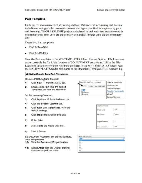
Create a PART-IN-ANSI Template.
1) Click New LI from the Menu bar. New SOLIDWORKS Document Default Templates
File Locations
2) Double-click Part from the default plates Tutorial MY-TEMPLATES
~~-------1 FeatureManager
Templates tab from the Menu bar. 1
1m Soin ox Increments
l~mbly I
~ Drawing VieVI '--
Set Dimensioning Standard.
Backup/Recover
3) Click Options {§} from the Menu bar.
4) Click the System Options tab.
Length increments
5) Click Spin Box Increments. View the
default settings. English units: 10.1oin
6) Click inside the English units box. Metric units: 12.somm
7) Enter.10in.
Angle increments:
8) Click inside the Metric units box.
Time increments: I 0.1 Os
9) Enter 2.50mm.
Set Document Properties. Set drafting standard, Overall drafting standard
units, and precision.
1 O) Click the Document Properties tab. ISO
DIN
JIS
11) Select ANSI from the Overall drafting BSI
GOST
standard drop-down menu. GB
PAGE 5 - 11