Page 384 - Subyek Computer Aided Design - [David Planchard] Engineering Design with SOLIDWORKS
P. 384

Extrude and Revolve Features                                                                                                                               Engineering Design with SOLIDWORKS® 2018


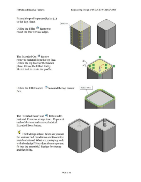
                                                Extend the profile perpendicular ( J_)


                                                to the Top Plane.


                                                                                                                                                                               Radius:  O.Sin


                                                Utilize the Fillet  1:9  feature to


                                                round the four vertical edges.


                                                The Extruded Cut  fJ  feature                                                                                                                                                                                                                 .


                                                removes material from the top face.


                                                Utilize the top face for the Sketch


                                                plane. Utilize the Offset Entity


                                                Sketch tool to create the profile.


                                                Utilize the Fillet feature  lB to round the top narrow                                                                                                                                 Radius:  0.05in


                                                face.


                                                The Extruded Boss/Base  ~ feature adds


                                                material. Conserve design time.  Represent


                                                each of the terminals as a cylindrical


                                                Extruded Boss feature.


                                                   , ,/


                                                  -;Q~ Think design intent. When do you use


                                                the various End Conditions and Geometric


                                                sketch relations? What are you trying to do


                                                with the design? How does the component


                                                fit into the assembly? Design for change


                                                and flexibility.


                                                                                                                                                                                PAGE5-16
   379   380   381   382   383   384   385   386   387   388   389