
Page 388 - Subyek Computer Aided Design - [David Planchard] Engineering Design with SOLIDWORKS
P. 388
Extrude and Revolve Features Engineering Design with SOLIDWORKS® 2018
, 1 /
;Q~ Modify the Spin Box Increments in System Options to
display different increments in
the on-screen ruler.
Fit the part to the Graphics window. ...
...
71) Press the f key. ~
...
...
Rename the Boss-Extrude1 feature.
72) Rename Boss-Extrude1 to
Base Extrude.
Save the BATTERY.
73) Click Save ii.
Modify the BATTERY.
74) Click Base Extrude from the
FeatureManager. lnstant3D
is activated by default.
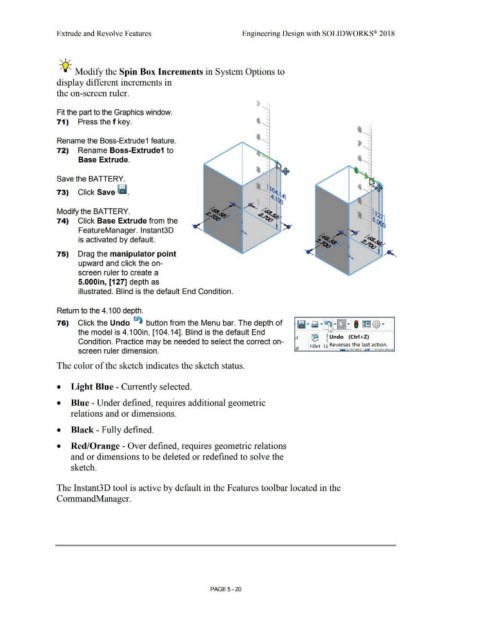
75) Drag the manipulator point
upward and click the on-
screen ruler to create a
5.000in, [127] depth as
illustrated. Blind is the default End Condition.
Return to the 4.100 depth.
76) Click the Undo ~ button from the Menu bar. The depth of
the model is 4.1 OOin, [104.14]. Blind is the default End
(E ~ Undo (Ctrl +Z)
Condition. Practice may be needed to select the correct on-
Fillet Lii Reverses the last action.
screen ruler dimension. --c;, I U I I.. I f t..'-,.(""::>~
The color of the sketch indicates the sketch status.
• Light Blue - Currently selected.
• Blue - Under defined, requires additional geometric
relations and or dimensions.
• Black - Fully defined.
• Red/Orange - Over defined, requires geometric relations
and or dimensions to be deleted or redefined to solve the
sketch.
The Instant3D tool is active by default in the Features toolbar located in the
CommandManager.
PAGE 5-20