
Page 392 - Subyek Computer Aided Design - [David Planchard] Engineering Design with SOLIDWORKS
P. 392
Extrude and Revolve Features Engineering Design with SOLIDWORKS® 2018
, 1 /
;Q~ A leading zero is displayed in the spin box. For
inch dimensions less than 1, the leading zero is not +
displayed in the part dimension in the ANSI standard.
t
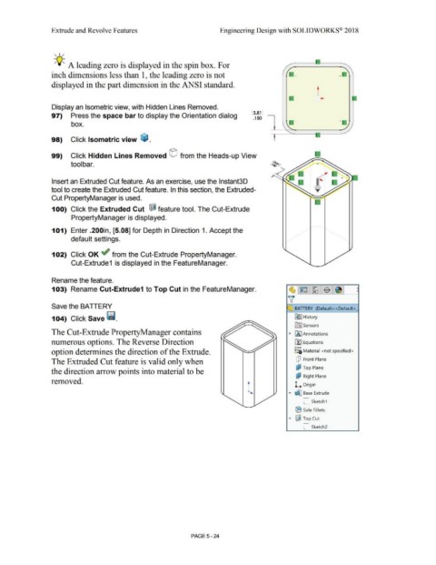
Display an Isometric view, with Hidden Lines Removed.
[ 3.81 ]
97) Press the space bar to display the Orientation dialog
.150
+ +
box.
98) Click Isometric view ~ .
99) Click Hidden Lines Removed © from the Heads-up View
tool bar.
Insert an Extruded Cut feature. As an exercise, use the lnstant3D
tool to create the Extruded Cut feature. In this section, the Extruded-
Cut PropertyManager is used.
100) Click the Extruded Cut ~ feature tool. The Cut-Extrude
PropertyManager is displayed.
101) Enter .200in, [5.08] for Depth in Direction 1. Accept the
default settings.
102) Click OK ~ from the Cut-Extrude PropertyManager.
Cut-Extrude1 is displayed in the FeatureManager.
Rename the feature.
103) Rename Cut-Extrude1 to Top Cut in the FeatureManager.
Save the BATIERY BA TIERY (Default< <Default>_
104) Click Save f!i. [e I History
iflJ Sensors
The Cut-Extrude PropertyManager contains • iAJ Annotations
numerous options. The Reverse Direction il:] Equations
o-
option determines the direction of the Extrude. ~:::a Material <not specified>
The Extruded Cut feature is valid only when dJ Front Plane
d,l Top Plane
the direction arrow points into material to be
&;? Right Plane
removed.
l ..... ~ Base Extrude
L Origin
C_ Sketch1
® Side Fillets
..... ~ Top Cut
C_ sketch2
PAGE 5-24