
Page 395 - Subyek Computer Aided Design - [David Planchard] Engineering Design with SOLIDWORKS
P. 395
Engineering Design with SOLIDWORKS® 2018 Extrude and Revolve Features
Calculate the depth of the extrusion: For inches: 4.500in - ( 4.1 OOin Base-Extrude
height - .200in Offset cut depth)= .600in. The depth of the extrusion is .600in.
For millimeters: 114.3mm - (104.14mm Base-Extrude height - 5.08mm Offset
cut depth)= 15.24mm. The depth of the extrusion is 15.24mm.
I Activity: BATTERY Part - Extruded Boss Feature
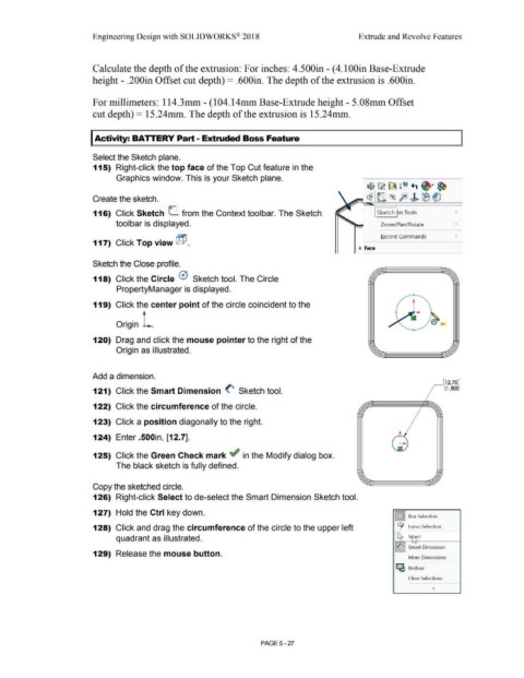
Select the Sketch plane.
115) Right-click the top face of the Top Cut feature in the
Graphics window. This is your Sketch plane.
Create the sketch.
116) Click Sketch L. from the Context toolbar. The Sketch I Sketch ~n Tools
toolbar is displayed. Zoom/Pan/Rotate
Recent Commands •
117) Click Top view ~ .
t Face
Sketch the Close profile.
118) Click the Circle 0 Sketch tool. The Circle
PropertyManager is displayed.
119) Click the center point of the circle coincident to the
Origin , .
120) Drag and click the mouse pointer to the right of the
Origin as illustrated.
Add a dimension.
_ [12.70]
121) Click the Smart Dimension <' Sketch tool. (/) .500
122) Click the circumference of the circle.
123) Click a position diagonally to the right.
124) Enter .500in, [12.7].
125) Click the Green Check mark ~ in the Modify dialog box.
The black sketch is fully defined.
Copy the sketched circle.
126) Right-click Select to de-select the Smart Dimension Sketch tool.
127) Hold the Ctrl key down.
J 1::::1 Box Selection
128) Click and drag the circumference of the circle to the upper left 9 Lasso Selection
quadrant as illustrated. t:t S~ct
!<'I sm'art Dimension
129) Release the mouse button.
More Dimensions
c:e Redraw
Clear Selections
PAGE5-27