
Page 391 - Subyek Computer Aided Design - [David Planchard] Engineering Design with SOLIDWORKS
P. 391
Engineering Design with SOLIDWORKS® 2018 Extrude and Revolve Features
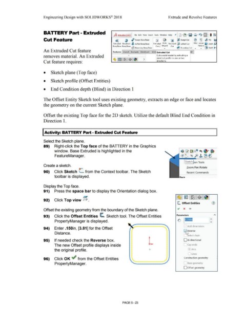
BATTERY Part - Extruded
tfSsOLIDWORKS File Edit View Insert Tools Window Help :,t [J ·~ ·,il·~ ·l:t)·!\:})·, I ~
~
Cut Feature ~ a I Swept Boss/Base ~ ~ ~ l:J; Swept Cut ® ~~ ~ Rib Iii
Extruded Revolved ~ Lofted Boss/Base Extru~d Hole Revolved @ Lofted Cut Fillet Linear fi:J Draft pe
Boss/Base Boss/Base ~ Cutl,..,r Wizard Cut ~ Pattern ~ .1.-
V Boundary Boss/Base • v Boundary Cut • • \J;l!I Shell ii,
An Extruded Cut feature Features Sketch Evaluate DimXpert SOLlj Extruded Cut D
removes material. An Extruded l Cuts a solid model by extruding a
sketched profile in one o r two
Cut feature requires: directions.
• Sketch plane (Top face)
• Sketch profile (Offset Entities)
• End Condition depth (Blind) in Direction 1
The Offset Entity Sketch tool uses existing geometry, extracts an edge or face and locates
the geometry on the current Sketch plane.
Offset the existing Top face for the 2D sketch. Utilize the default Blind End Condition in
Direction 1.
I Activity: BATTERY Part - Extruded Cut Feature
Select the Sketch plane.
89) Right-click the Top face of the BATTERY in the Graphics
window. Base Extruded is highlighted in the
FeatureManager.
Create a sketch.
Zoom/ Pan/Rotate
90) Click Sketch C from the Context toolbar. The Sketch Recent Commands
toolbar is displayed.
Display the Top face.
91) Press the space bar to display the Orientation dialog box.
92) Click Top view @.
~ Offset Entities
Offset the existing geometry from the boundary of the Sketch plane.
93) Click the Offset Entities ~ Sketch tool. The Offset Entities
PropertyManager is displayed.
Add dimensions
94) Enter .150in, [3.81] for the Offset
8l,feverse
Distance.
- ~ elect chain
95) If needed check the Reverse box. DBi-directional
The new Offset profile displays inside L-.1 Cap ends
the original profile. Arcs
Lines
96) Click OK ~ from the Offset Entities Construction geometry:
PropertyManager. Base geometry
D Offset geometry
PAGE5-23