
Page 386 - Subyek Computer Aided Design - [David Planchard] Engineering Design with SOLIDWORKS
P. 386
Extrude and Revolve Features Engineering Design with SOLIDWORKS® 2018
I Activity: BATTERY Part - Create the Extruded Base Feature
Create a New part.
New SOLID ORKS Document
43) Click New LI from the Menu bar.
44) Click the MY-TEMPLATES tab. The MY-TEMPLATES tab was !ID PART-ANSI-IN
~m11141~t
created earlier in the book. ~PAA-MM-ISO
IID ASM-1 N-ANSI
45) Double-click PART-IN-ANSI, [PART-MM-ISO]. !ID ASM-IN-ISO
!ID ASM-MM-ANSI
IID ASM·MM·ISO
ml A-ANSI-MM
Save the part. Enter name and description. ~ 8-ANSI-MM
46) Click Save ii.
File name: I BATIERY.SLDPRT
47) Select PROJECTS for Save in folder.
Save as type: Part (*.prt;*.sldprt)
Description: BATIE RY, 6-VOLT I
48) Enter BATTERY for File name.
49) Enter BATTERY, 6-VOLT for Description. @save as lncluc
O Save as copy and continue Add
O Save as copy and open Add
50) Click Save. The Battery FeatureManager is displayed.
• Hide Folders
Select the Sketch plane.
51) Right-click Top Plane from the FeatureManager. This is (&1~1~1$ 1~1 >
your Sketch plane. ~
~ BATIERY (Default< <Default>_
Sketch the 20 Sketch profile centered at the Origin. ~ I History
@!I Sensors
52) Click Sketch L from the Context toolbar. The Sketch •
toolbar is displayed. Ul I Annotations
IEf:I Equations
o-
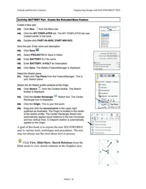
53) Click the Center Rectangle m1 Sketch tool. The Center ~:O Material <not specified>
Rectangle icon is displayed. Q Fro [GJ ® = f
.
~ To ' feJ ..»
54) Click the Origin. This is your first point. Q Rig Fe Sketch op Plane)
55) Drag and click the second point in the upper right L ori ~ D .iD Sketch On Pl,
quadrant as illustrated. The Origin is located in the center
of the sketch profile. The Center Rectangle Sketch tool / · 0 · N · fl ~ ©
automatically applies equal relations to the two horizontal Irim Convert
~ • "') • (9 • /A.. Entities Entities
and two vertical lines. A midpoint relation is automatically
O Corner Rectangle
applied to the Origin.
~ Center Rectangle
A goal of this book is to expose the new SOLIDWORKS '<), 3 Point Corner Rectangle
user to various tools, techniques and procedures. The text ~ 3 Point Center Rectangle
may not always use the most direct tool or process. ll Parallelogram
, 1 /
;Q~ Click View, Hide/Show, Sketch Relations from the
Main menu to view sketch relations in the Graphics area.
..,
I ·,
·,
I ·,
I
;' ·,
I ' \
;'
·,
. ·,
,/ ·,
,/
., ____ __ _;':,,
PAGE 5 - 18