
Page 381 - Subyek Computer Aided Design - [David Planchard] Engineering Design with SOLIDWORKS
P. 381
Engineering Design with SOLIDWORKS® 2018 Extrude and Revolve Features
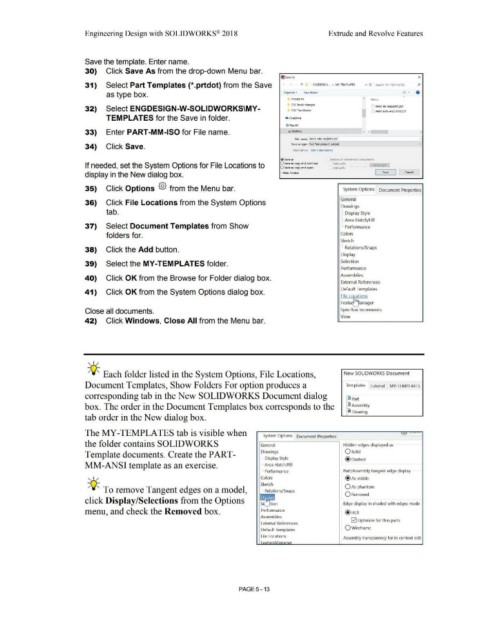
Save the template. Enter name.
30) Click Save As from the drop-down Menu bar.
~ Save As x
31) Select Part Templates {*.prtdot) from the Save 1' • ENGOESIGN-_, > MY-TEMPLATES v C, Soarch MY-TEMPLATES P
as type box. Organize • New folder = • 0
PROJECTS Nome
SOC book changes PART ·IN·ANSI.PRTOOT
32) Select ENGDESIGN-W-SOLIDWORKS\MY- SOC Text Folder I PART-MM-ANSI.PRTOOT
TEMPLATES for the Save in folder. 6 0n•Orive
Iii This PC
-
33) Enter PART-MM-ISO for File name. • O•sklop v < )
File name: I PART ·MM·ISo(PRTOOT
34) Click Save. Save as type: Part Templates (".prtdot)
Description: Add a description
®save •• Include all refeienced components
If needed, set the System Options for File Locations to O Save as copy and continue Add prefix
O Save as copy and open
Add suffix
display in the New dialog box. • Hide Folders Save Cancel
35) Click Options {§} from the Menu bar. System Options Document Properties
General
36) Click File Locations from the System Options
Drawings
tab. I Display Style
;
1-Area Hatch/Fill
37) Select Document Templates from Show L Performance
folders for. Colors
Sketch
i
38) Click the Add button. '· Relations/Snaps
Display
39) Select the MY-TEMPLATES folder. Selection
Performance
Assemblies
40) Click OK from the Browse for Folder dialog box.
External References
Default Templates
41) Click OK from the System Options dialog box.
File Lo ·ations
Feat~lanager
Close all documents. Spin Box Increments
View
42) Click Windows, Close All from the Menu bar.
, ,/
-;Q~ Each folder listed in the System Options, File Locations, New SOLIDWORKS Document
Document Templates, Show Folders For option produces a Templates Tutorial MY-TEMPLATES
corresponding tab in the New SOLIDWORKS Document dialog ~ Part
box. The order in the Document Templates box corresponds to the I Assembly
liiil Drawing
tab order in the New dialog box.
The MY-TEMPLATES tab is visible when
System Options Document Properties
the folder contains SOLIDWORKS General Hidden edges displayed as
Template documents. Create the PART- Drawings Osolid
I Display Style @ Dashed
MM-ANSI template as an exercise. ~· Area Hatch/Fill
!
L Performance Part/Assembly tangent edge display
, ,/ Colors @ As visible
Sketch
-;Q~ To remove Tangent edges on a model, L. Relations/Snaps 0As phantom
QRemoved
click Display /Selections from the Options
~ n Edge display in shaded with edges mode
menu, and check the Removed box. Performance @ HLR
Assemblies
G2] Optimize for thin parts
External References
Qwireframe
Default Templates
File Locations
Assembly transparency for in context edit
PAGE5 - 13