
Page 397 - Subyek Computer Aided Design - [David Planchard] Engineering Design with SOLIDWORKS
P. 397
Engineering Design with SOLIDWORKS® 2018 Extrude and Revolve Features
, ,/
-;Q~ Press the Enter key to accept the value in _ [12.70]
0 .500
the Modify dialog box. The Enter key replaces
the Green Check mark.
Add an angular dimension.
[25.40] ------
1.000
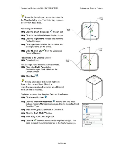
144) Click the Smart Dimension <' Sketch tool.
145) Click the centerline between the two circles.
146) Click the Right Plane (vertical line) from the
FeatureManager.
147) Click a position between the centerline and
the Right Plane, off the profile.
450
_ [12.70]
148) Enter 45. Click OK ~ from the Dimension 0 .500
PropertyManager.
Fit the model to the Graphics window.
149) Press the f key. [25.40] ______
1.000 '
Hide the Right Plane if needed. Save the model.
150) Right-click Right Plane in the
FeatureManager. Click Hide from the
Context toolbar.
151) Click Save Ii.
, ,/
-;Q~ Create an angular dimension between
three points or two lines. Sketch a
centerline/construction line when an additional
point or line is required.
Display an Isometric view. Insert an Extruded Boss feature.
152) Click Isometric view ~ .
153) Click the Extruded Boss/Base ~ feature tool. The Boss-
Extrude PropertyManager is displayed. Blind is the default End Direction 1
Condition Type. II] Blind v
-----~
154) Enter .600in, [15.24] for Depth in Direction 1. ~
155) Click the Draft ON/OFF button. 1
~ o.600in
156) Enter 5deg in the Draft Angle box. [;21 Merge result
157) Click OK if from the Boss-Extrude PropertyManager. The
Boss-Extrude2 feature is displayed in the FeatureManager. Draft On/Off tward
Direction 2 v
PAGE5 - 29