
Page 375 - Subyek Computer Aided Design - [David Planchard] Engineering Design with SOLIDWORKS
P. 375
Engineering Design with SOLIDWORKS® 2018 Extrude and Revolve Features
Develop design intent as you sketch with
Add Relations
Geometric relations. Sketch relations are
a - Horizontal
geometric constraints between sketch
I Vertical
entities or between a sketch entity and a ,,. Collinear
/
plane, axis, edge, or vertex. Relations can I J_ Perpendicular
be added automatically or manually. ~
Parallel
- Egual
-
A rectangle contains Horizontal, Vertical, o------,a 'c fix
and Perpendicular automatic Geometric
relations. Apply design intent using added
f----- 3.00 ----
Geometric relations. Example: Horizontal,
Vertical, Collinear, Perpendicular, Parallel
etc.
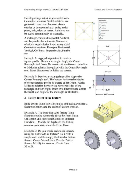
Example A: Apply design intent to create a 2.00
square profile. Sketch a rectangle. Apply the Center
Rectangle tool. Note: No construction reference centerline
or Midpoint relation is required with the Center Rectangle
tool. Insert dimensions to define the square. ¢ 4
Example B: Develop a rectangular profile. Apply the
) _
Comer Rectangle tool. The bottom horizontal midpoint ,. -, - -,
.-
-.
of the rectangular profile is located at the Origin. Add a
Midpoint relation between the horizontal edge of the
1 1
rectangle and the Origin. Insert two dimensions to define 16.50
the width and height of the rectangle as illustrated.
39.50
2. Design Intent in the Feature
Build design intent into a feature by addressing symmetry,
feature selection, and the order of feature creation.
Example A: The Boss-Extrude 1 feature (Base
feature) remains symmetric about the Front Plane.
Utilize the Mid Plane End Condition option in
Direction 1. Modify the depth and the feature
remains symmetric about the Front Plane.
Example B: Do you create each tooth separate
using the Extruded Cut feature? No. Create a
single tooth and then apply the Circular Pattern
feature. Create 34 teeth for a Circular Pattern
feature. Modify the number of teeth from
32 to 24.
PAGE 5 - 7