
Page 43 - Subyek Computer Aided Design - [David Planchard] Engineering Design with SOLIDWORKS
P. 43
Engineering Design with SOLIDWORKS® 2018 Overview of SOLID WORKS® and the User Interface
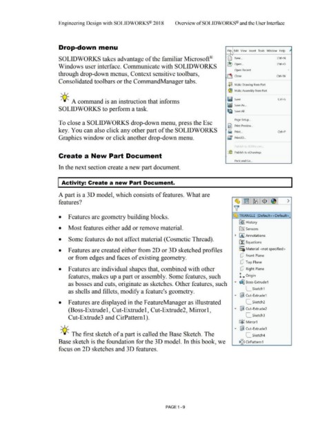
Drop-down menu
Fil , Edit View Insert Tools Window Help _,.
"
r.::; '
SOLIOWORKS takes advantage of the familiar Microsoft® L) New .. . Ctrl+N
Windows user interface. Communicate with SOLIOWORKS ~ Open .. . Ctrl+O
Open Recent •
through drop-down menus, Context sensitive toolbars,
~ Close Ctrl +W
Consolidated toolbars or the CommandManager tabs.
2~ Make Drawing from Part
, ,/ ,® Make Assembly from Part
-;Q~ A command is an instruction that informs ~ ij Save Ctrl+S
5
W SaveAs ...
SOLIOWORKS to perform a task.
U1& Save AII
Page Setup ...
To close a SOLIOWORKS drop-down menu, press the Esc
~ Print Preview ...
key. You can also click any other part of the SOLIOWORKS ~ Print ... Ctrl+P
3
Graphics window or click another drop-down menu. [ f Print3D ...
Publ h ~[.\\.' '\ -:ir~
{(6 Publish to eDrawings
Create a New Part Document
Pack and Go ...
In the next section create a new part document.
Activity: Create a new Part Document.
A part is a 30 model, which consists of features. What are
features? ~l~ l~l$ i~I >
~
• Features are geometry building blocks. ~ TRIANGLE (Default< <Default> j
~ I History
• Most features either add or remove material. [fl:] Sensors
~ [A I Annotations
• Some features do not affect material (Cosmetic Thread).
~ Equations
o-
• Features are created either from 20 or 30 sketched profiles ~:a Material <not specified>
[!] Front Plane
or from edges and faces of existing geometry.
(!] Top Plane
• Features are individual shapes that, combined with other [!] Right Plane
features, makes up a part or assembly. Some features, such l. Origin
as bosses and cuts, originate as sketches. Other features, such ... ~ Boss-Extrude1
L_ Sketch1
as shells and fillets, modify a feature's geometry.
... ~ Cut- Extrude1
• Features are displayed in the FeatureManager as illustrated L_ Sketch2
(Boss-Extrude 1, Cut-Extrude 1, Cut-Extrude2, Mirror 1, ... ~ Cut-Extrude2
Cut-Extrude3 and CirPatteml). L_ Sketch3
G3~ Mirror1
, ,/
... ~ Cut- Extrude3
-;Q~ The first sketch of a part is called the Base Sketch. The L_ Sketch4
Base sketch is the foundation for the 30 model. In this book, we Iii~(] CirPattern1
focus on 20 sketches and 30 features.
PAGE 1 - 9