
Page 29 - Engineering drawing from first principles using AutoCAD
P. 29
22 Engineering drawinq [rom first principles
Inks evaporate and papers absorb at different rates, so some experimentation may be
necessary with different combinations of papers and printers to obtain contrasting line
thicknesses. The drawings in this book are designed to fit A4 size sheets and I hope you
will copy them to improve your draughting knowledge and efficiency. Perhaps the
evidence of your ability will come in handy when seeking employment.
The British Standard linework recommendations are shown in Table 1.1 by kind permis-
sion of The British Standards Institution. Applications of the various linetypes are shown
in Fig. 1.19.
Coinciding lines
It is often the case that two or more lines will coincide, and the following order of priority
is recommended by BS 308 (Table 1.1).
1. visible outlines and edges (types A);
2. hidden outlines and edges (types E or F):
3. cutting planes (type HI);
4. centre lines, etc. (types G and B7);
5. outlines and edges of adjacent parts, etc. (types I();
6. projection lines (type B3).
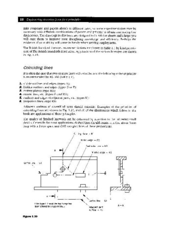
Adjacent outlines of assembled parts should coincide. Examples of the priorities of
coinciding lines are shown in Fig. 1.20, and all of the illustrations which follow in the
book are applications of these principles.
The quality of finished linework can be enhanced by attention to the, following small
details. Generally for most applications, dashed lines should consist of a line about 3mm
long with a 2 mm space and CAD can give lines of these proportions.
cutting plane - HI
Hidden edge - F2
Centroidal line - K3
Visible edge - A2
Centre line - GI ~
I
I
A---f L
-----~ Centre line - GI
(The type F Iine at theto~ flange has .
been altered to a type H line.) Adjacent part A-A
outline - K1
Figure 1.20