
Page 86 - Enhanced Oil Recovery in Shale and Tight Reservoirs
P. 86
Asphaltene precipitation and deposition in a huff-n-puff process 73
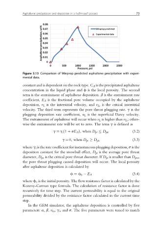
Figure 3.13 Comparison of Winprop predicted asphaltene precipitation with experi-
mental data.
constant and is dependent on the rock type. C A is the precipitated asphaltene
concentration in the liquid phase and f is the local porosity. The second
term is the entrainment of asphaltene deposition. b is the entrainment rate
coefficient, E A is the fractional pore volume occupied by the asphaltene
deposition, v L is the interstitial velocity, and v Lc is the critical interstitial
velocity. The third term represents the pore throat plugging rate. g is the
plugging deposition rate coefficient, u L is the superficial Darcy velocity.
The entrainment of asphaltene will occur when v L is higher than v Lc ; other-
wise the entrainment rate will be set to zero. The term g is defined as
g ¼ g ð1 þ sE A Þ; when D pt D ptc (3.2)
i
g ¼ 0; when D pt D ptc (3.3)
where g i is the rate coefficient for instantaneous plugging deposition, s is the
deposition constant for the snowball effect, D pt is the average pore throat
diameter, D ptc is the critical pore throat diameter. If D pt is smaller than D ptcr ,
the pore throat plugging caused deposition will occur. The local porosity
after asphaltene deposition is calculated by
(3.4)
0
f ¼ f E A
where f is the initial porosity. The flow resistance factor is calculated by the
0
Kozeny-Carman type formula. The calculation of resistance factor is done
recursively for time step. The current permeability is equal to the original
permeability divided by the resistance factor calculated in the current time
step.
In the GEM simulator, the asphaltene deposition is controlled by five
parameters: a, b, v Lc , g i , and s. The five parameters were tuned to match