
Page 151 - Entrophy Analysis in Thermal Engineering Systems
P. 151
Entropy and fuel cells 145
_
η ¼ W net (9.44)
_ n H 2 LHV
where
_ (9.45)
_ W FC,ac ¼ η W FC,dc
inv
and η inv denotes the DC-AC inverter efficiency assumed to be 0.95 [6] in the
present calculations.
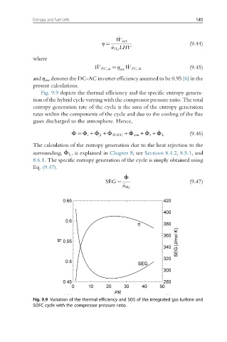
Fig. 9.9 depicts the thermal efficiency and the specific entropy genera-
tion of the hybrid cycle varying with the compressor pressure ratio. The total
entropy generation rate of the cycle is the sum of the entropy generation
rates within the components of the cycle and due to the cooling of the flue
gases discharged to the atmosphere. Hence,
_ _ _ _ _ _ _ (9.46)
Φ ¼ Φ c + Φ fc + Φ SOFC + Φ com + Φ t + Φ L
The calculation of the entropy generation due to the heat rejection to the
_
surrounding, Φ L , is explained in Chapter 8; see Sections 8.4.2, 8.5.1, and
8.6.1. The specific entropy generation of the cycle is simply obtained using
Eq. (9.47).
_
Φ
SEG ¼ (9.47)
_ n H 2
Fig. 9.9 Variation of the thermal efficiency and SEG of the integrated gas turbine and
SOFC cycle with the compressor pressure ratio.