
Page 148 - Entrophy Analysis in Thermal Engineering Systems
P. 148
142 Entropy Analysis in Thermal Engineering Systems
fuel cell is 0.795 whereas that of the Carnot engine is 0.7. It is important to
realize that an ideal fuel cell with an efficiency greater than the Carnot effi-
ciency is not in violation of the second law; a natural law that prohibits com-
plete conversion of heat to mechanical work.
9.5 SEG in a hybrid cycle
In this last section, the application of the SEG analysis is demonstrated
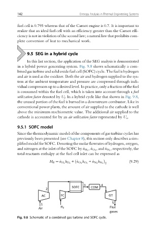
in a hybrid power generating system. Fig. 9.8 shows schematically a com-
bined gas turbine and solid oxide fuel cell (SOFC) cycle. The fuel is hydrogen
and air is used as the oxidizer. Both the air and hydrogen supplied to the sys-
tem at the ambient temperature and pressure are compressed through indi-
vidual compressors up to a desired level. In practice, only a fraction of the fuel
is consumed within the fuel cell, which is taken into account through a fuel
utilization factor denoted by U f . In a hybrid cycle like that shown in Fig. 9.8,
the unused portion of the fuel is burned in a downstream combustor. Like in
conventional power plants, the amount of air supplied to the cathode is well
above the minimum stochiometric value. The additional air supplied to the
cathode is accounted for by an air utilization factor represented by U a .
9.5.1 SOFC model
Since the thermodynamic model of the components of gas turbine cycles has
previously been presented (see Chapter 8), this section only describes a sim-
plified model for SOFC. Denoting the molar flowrates of hydrogen, oxygen,
, respectively, the
and nitrogen at the inlet of the SOFC by _n H 2 , _n O 2 , and _n N 2
total reactants enthalpy at the fuel cell inlet can be expressed as
ð h Þ (9.29)
H R ¼ _n H 2 H 2 + _n O 2 O 2 + _n N 2 N 2 2
h
h
Fig. 9.8 Schematic of a combined gas turbine and SOFC cycle.