
Page 146 - Entrophy Analysis in Thermal Engineering Systems
P. 146
140 Entropy Analysis in Thermal Engineering Systems
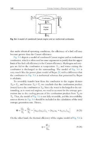
Fig. 9.6 A model of combined Carnot engine and an isothermal combustor.
that under identical operating conditions, the efficiency of a fuel cell may
become greater than the Carnot efficiency.
Fig. 9.6 depicts a model of combined Carnot engine and an isothermal
combustor, which is often used in some arguments to justify that the upper
limit of the fuel cell efficiency is the Carnot efficiency. Hydrogen and oxy-
gen are fed to the combustor at temperature T C , and water exiting the
combustor is discharged to the surrounding. The model of Fig. 9.6 is
very much like the power plant model of Bejan [5] with a difference that
the combustor in Fig. 9.6 is isothermal whereas that presented by Bejan
is adiabatic.
To reversibly transfer heat from the combustor to the engine dictates
T H ¼T C , and because T H >T L we conclude that the combustion product
(water) leaves the combustor at T H . Since the water is discharged to the sur-
rounding, as in most real engines, we need to account for the entropy gen-
eration due to the cooling process of the combustion product from T H to
T L . Thus, the model of Fig. 9.6 is not fully reversible, and the irreversibility
sources shown in Fig. 9.6 should be included in the calculation of the total
entropy generation rate. Hence,
_ _ h i
_ Q Q
s Þ
ð
ð
Φ ¼ T L L + T L C + _n H 2 O s H 2 O Þ _n H 2 H 2 + _n O 2 O 2 T H (9.25)
s
T L
On the other hand, the thermal efficiency of the engine model of Fig. 9.6 is
η ¼ _ W C (9.26)
_
Q
in