
Page 142 - Entrophy Analysis in Thermal Engineering Systems
P. 142
136 Entropy Analysis in Thermal Engineering Systems
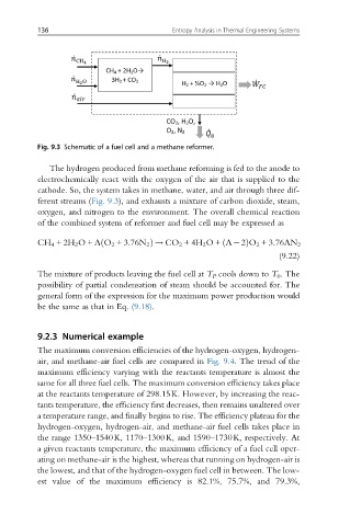
Fig. 9.3 Schematic of a fuel cell and a methane reformer.
The hydrogen produced from methane reforming is fed to the anode to
electrochemically react with the oxygen of the air that is supplied to the
cathode. So, the system takes in methane, water, and air through three dif-
ferent streams (Fig. 9.3), and exhausts a mixture of carbon dioxide, steam,
oxygen, and nitrogen to the environment. The overall chemical reaction
of the combined system of reformer and fuel cell may be expressed as
ð
CH 4 +2H 2 O+ Λ O 2 +3:76N 2 Þ ! CO 2 +4H 2 O+ Λ 2ð ÞO 2 +3:76ΛN 2
(9.22)
The mixture of products leaving the fuel cell at T P cools down to T 0 . The
possibility of partial condensation of steam should be accounted for. The
general form of the expression for the maximum power production would
be the same as that in Eq. (9.18).
9.2.3 Numerical example
The maximum conversion efficiencies of the hydrogen-oxygen, hydrogen-
air, and methane-air fuel cells are compared in Fig. 9.4. The trend of the
maximum efficiency varying with the reactants temperature is almost the
same for all three fuel cells. The maximum conversion efficiency takes place
at the reactants temperature of 298.15K. However, by increasing the reac-
tants temperature, the efficiency first decreases, then remains unaltered over
a temperature range, and finally begins to rise. The efficiency plateau for the
hydrogen-oxygen, hydrogen-air, and methane-air fuel cells takes place in
the range 1350–1540K, 1170–1300K, and 1590–1730K, respectively. At
a given reactants temperature, the maximum efficiency of a fuel cell oper-
ating on methane-air is the highest, whereas that running on hydrogen-air is
the lowest, and that of the hydrogen-oxygen fuel cell in between. The low-
est value of the maximum efficiency is 82.1%, 75.7%, and 79.3%,