
Page 138 - Entrophy Analysis in Thermal Engineering Systems
P. 138
132 Entropy Analysis in Thermal Engineering Systems
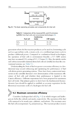
Fig. 9.1 The basic operating principles and components of a fuel cell.
Table 9.1 Comparison of the measured NO x and CO emissions
(g/MWh) from fuel cells and conventional technologies [3].
Condensing
Fuel cell boiler CHP engine
1–4 58 30–270
NO x
CO 1–8 43 10–50
generation where the hot reaction products can be used in a bottoming cycle
such as a gas turbine cycle, a steam cycle, or a combined gas/steam cycle to
produce additional power. Compared to combustion-based technologies,
the operation of fuel cells is environment friendly; a 0.7–1kW system
may have an annual CO 2 saving of 1.3–1.9 tones [3]. Also, the nitride oxides
and carbon monoxide emissions from fuel cells are notably less than the con-
ventional systems; see Table 9.1.
Understanding the limit of fuel-to-power conversion efficiency is a fun-
damental step toward enhancing and optimizing the performance of fuel
cell-driven power generating systems. There have been controversial state-
ments in the scientific literature over determination of the maximum effi-
ciency of fuel cells and whether their performance is limited to the
Carnot efficiency. Different expressions have been proposed for maximum
fuel cell work. Our primary goal is to show how the fundamental thermo-
dynamic laws should be applied to establish an accurate expression for the
theoretical maximum work of a hydrogen-fed fuel cell.
9.2 Maximum conversion efficiency
Consider a hydrogen fuel cell (Fig. 9.2) in which oxygen and hydro-
gen are fed to the cathode and anode, respectively. The operation of the fuel
cell is assumed to be steady state, adiabatic, and isobaric. The reactants enter
the fuel cell at temperature T R and pressure p 0 . The reaction product (water)