
Page 139 - Entrophy Analysis in Thermal Engineering Systems
P. 139
Entropy and fuel cells 133
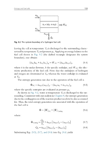
Fig. 9.2 The system boundary of a hydrogen fuel cell.
leaving the cell at temperature T P is discharged to the surrounding charac-
terized by temperature T 0 and pressure p 0 . Applying an energy balance to the
fuel cell shown in Fig. 9.2 (the dashed rectangle designates the system
boundary), one obtains
ð _ n H 2 H 2 h Þ ¼ _ W FC + _n H 2 O h H 2 O Þ (9.4)
ð
h
+ _n O 2 O 2 R
P
where _n is the molar flowrate, h the specific enthalpy, and _ W FC the elec-
tricity production of the fuel cell. Note that the enthalpies of hydrogen
and oxygen are determined at T R whereas the water enthalpy is evaluated
at T P .
The entropy generation rate due to the operation of the fuel cell is
_
ð
s Þ
ð
Φ FC ¼ _n H 2 O s H 2 O Þ _n H 2 H 2 + _n O 2 O 2 R (9.5)
s
P
where the specific entropies are evaluated at pressure p 0 .
As shown in Fig. 9.2, water at temperature T P is discharged to the sur-
rounding. Consistent with our analysis in Chapter 8, the entropy generation
due to the cooling process of the reaction product needs to be also accounted
for. Thus, the total entropy generation rate associated with the operation of
the fuel cell is
_
_
_
Φ ¼ Φ + Φ (9.6)
FC Cooling
where
_
_ Q 0
Φ Cooling ¼ + _n H 2 O s H 2 O Þ s H 2 O Þ (9.7)
ð
ð
0
T 0 P
_
ð
ð
Q ¼ _n H 2 O h H 2 O Þ h H 2 O Þ 0 (9.8)
0
P
Substituting Eqs. (9.5), (9.7), and (9.8) into Eq. (9.6) yields