
Page 56 - Entrophy Analysis in Thermal Engineering Systems
P. 56
48 Entropy Analysis in Thermal Engineering Systems
For compressible fluids, the specific volume and pressure are interrelated.
For example, in the case of an ideal gas where the state equation is pv¼R g T,
Eq. (4.9) can be expressed as
ð
(4.10)
dp
Δs ¼ R g
p
Note that dp<0 in Eqs. (4.9) and (4.10); thus, Δs>0. Because it was
assumed that the frictional heat remains in the fluid, Δs denotes the increase
in the entropy of the fluid.
4.4 Expansion
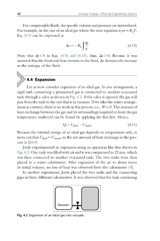
Let us now consider expansion of an ideal gas. In one arrangement, a
rigid tank containing a pressurized gas is connected to another evacuated
tank through a valve as shown in Fig. 4.2. If the valve is opened, the gas will
pass from the tank to the one that is in vacuum. If we take the entire arrange-
ment as a system, there is no work in this process, i.e., W¼0. The amount of
heat exchange between the gas and its surroundings required to keep the gas
temperature unaltered can be found by applying the first law. Hence,
(4.11)
Q ¼ U final U initial
Because the internal energy of an ideal gas depends on temperature only, it
turns out that U final ¼U initial , so the net amount of heat exchange in the pro-
cess is Q¼0.
Joule experimented air expansion using an apparatus like that shown in
Fig. 4.2. One tank was filled with air and it was compressed to 22atm, which
was then connected to another evacuated tank. The two tanks were then
placed in a water calorimeter. After expansion of the air to about twice
its initial volume, no loss of heat was observed from the calorimeter [4].
In another experiment, Joule placed the two tanks and the connecting
pipe in three different calorimeters. It was observed that the tank containing
Fig. 4.2 Expansion of an ideal gas into vacuum.