
Page 322 - Facility Piping Systems Handbook for Industrial, Commercial, and Healthcare Facilities
P. 322
SITE UTILITY SYSTEMS
6.44 CHAPTER SIX
Now that the basic watershed parameters have been established, the final design of
the storage basin can proceed. This method is not as accurate as the computer program
developed by the Soil Conservation Service for this purpose, but Eq. (6.6) will provide a
conservative approach based on average storage effects on peak discharges.
V × A
V = S (6.6)
B
12
where V = volume of storage basin, acre ft
B
V = volume of storage, watershed in
S
2
A = area of watershed, acres (note: 640 acres = 1 mi
12 = inches in 1 ft (for conversion of VS into acre ft)
Discussion:
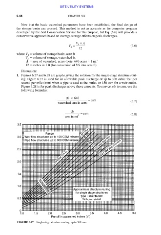
1. Figures 6.27 and 6.28 are graphs giving the solution for the single-stage structure rout-
ing. Figure 6.27 is used for an allowable peak discharge of up to 300 cubic feet per
second per mile (csm) when a pipe is used as the outlet, or 150 csm for a weir outlet.
Figure 6.28 is for peak discharges above those amounts. To convert cfs to csm, use the
following formulas:
cfs × 640
= csm
watershedarea inacres (6.7)
cfs
2 = csm (6.8)
area in mi
FIGURE 6.27 Single-stage structure routing, up to 300 csm.
Downloaded from Digital Engineering Library @ McGraw-Hill (www.accessengineeringlibrary.com)
Copyright © 2009 The McGraw-Hill Companies. All rights reserved.
Any use is subject to the Terms of Use as given at the website.