
Page 323 - Facility Piping Systems Handbook for Industrial, Commercial, and Healthcare Facilities
P. 323
SITE UTILITY SYSTEMS
SITE UTILITY SYSTEMS 6.45
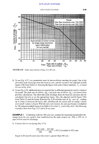
FIGURE 6.28 Single-stage structure routing, over 300 csm.
2. To use Fig. 6.27, two parameters must be known before entering the graph. One is the
allowable peak discharge from the basin in csm, and the second is the adjusted rainfall
figure (VR) from Table 6.5. Entering the figure with each of these numbers, V is found
S
for use in Eq. (6.6).
3. To use Fig. 6.28, additional steps are required due to different parameters used to construct
the graph. The peak rate of outflow (Q ) and peak rate of inflow (Q are known from
)
O I
previous calculations. The allowable peak discharge from the basin in csm must also be
calculated, but only to use the appropriate figure. Also, the adjusted rainfall figure (VR)
from Table 6.5 must be found. Entering Fig. 6.28 with the ratio of Q over Q , reading
O I
up to where it intersects the heavy line, and then left, the actual ratio of storage volume
over runoff volume is found. With the ratio now known, the ratio just found is multiplied
by VR (adjusted rainfall figure from Table 6.5) to find V used in Eq. (6.6). The following
S
examples show how Figs. 6.27 and 6.28 are used.
EXAMPLE 1 Continuing with the 300-acre site, assume the maximum permissible dis-
charge from the site equal to that established for the undeveloped site. This is 399 cfs. A
pipe will be used for discharge.
1. Convert cfm to csm [using (Eq. 6.7)]:
×
399 640 255 360
,
= = 851 2 (rounded to 852 ccsm)
.
300 300
Figure 6.28 must be used since the result is greater than 300 csm.
Downloaded from Digital Engineering Library @ McGraw-Hill (www.accessengineeringlibrary.com)
Copyright © 2009 The McGraw-Hill Companies. All rights reserved.
Any use is subject to the Terms of Use as given at the website.