
Page 80 - Facility Piping Systems Handbook for Industrial, Commercial, and Healthcare Facilities
P. 80
PIPING
2.30 CHAPTER TWO
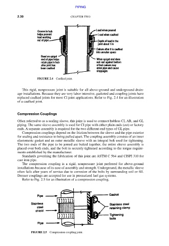
FIGURE 2.4 Caulked joint.
This rigid, nonpressure joint is suitable for all above-ground and underground drain-
age installations. Because they are very labor intensive, gasketed and coupling joints have
replaced caulked joints for most CI joint applications. Refer to Fig. 2.4 for an illustration
of a caulked joint.
Compression Couplings
Often referred to as a sealing sleeve, this joint is used to connect hubless CI, AR, and GL
piping. The same sleeve assembly is used for CI pipe with either plain ends (cut) or factory
ends. A separate assembly is required for the two different end types of GL pipe.
Compression couplings depend on the friction between the sleeve and the pipe exterior
for sealing and resistance to being pulled apart. The coupling assembly consists of an inner
elastomeric gasket and an outer metallic sleeve with an integral bolt used for tightening.
The two ends of the pipe to be joined are butted together, the entire sleeve assembly is
placed over both ends, and the bolt is securely tightened according to the torque require-
ments established by the manufacturer.
Standards governing the fabrication of this joint are ASTM C 564 and CISPI 310 for
cast iron pipe.
The compression coupling is a rigid, nonpressure joint preferred for above-ground
installations because of its ease of assembly and strength. Underground, the metallic sleeve
often fails after years of service due to corrosion of the bolts by surrounding soil or fill.
Dresser couplings are accepted for use in pressurized fuel gas systems.
Refer to Fig. 2.5 for an illustration of a compression coupling.
FIGURE 2.5 Compression coupling joint.
Downloaded from Digital Engineering Library @ McGraw-Hill (www.accessengineeringlibrary.com)
Copyright © 2009 The McGraw-Hill Companies. All rights reserved.
Any use is subject to the Terms of Use as given at the website.