
Page 191 - Failure Analysis Case Studies II
P. 191
176
L
b
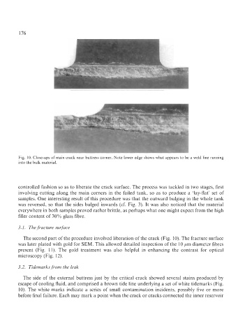
Fig. 10. Close-ups of main crack near buttress corner. Note lower edge shows what appears to be a weld line running
into the bulk material.
controlled fashion so as to liberate the crack surface. The process was tackled in two stages, first
involving cutting along the main corners in the failed tank, so as to produce a ‘lay-flat’ set of
samples. One interesting result of this procedure was that the outward bulging in the whole tank
was reversed, so that the sides bulged inwards (cf. Fig. 3). It was also noticed that the material
everywhere in both samples proved rather brittle, as perhaps what one might expect from the high
filler content of 30% glass fibre.
3.1. The fracture surface
The second part of the procedure involved liberation of the crack (Fig. 10). The fracture surface
was later plated with gold for SEM. This allowed detailed inspection of the 10 ,um diameter fibres
present (Fig. 11). The gold treatment was also helpful in enhancing the contrast for optical
microscopy (Fig. 12).
3.2. Tidemarks from the leak
The side of the external buttress just by the critical crack showed several stains produced by
escape of cooling fluid, and comprised a brown tide line underlying a set of white tidemarks (Fig.
10). The white marks indicate a series of small contamination incidents, possibly five or more
before final failure. Each may mark a point when the crack or cracks connected the inner reservoir