
Page 188 - Failure Analysis Case Studies II
P. 188
173
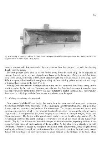
Fig. 6. Close-up of top inner surface of failed box showing complex flow lines (open arrow, left) and sprue (S). Cold
slug near sprue at centre (open arrow, right).
shows a serious weld line surrounded by an extensive flow line pattern, the weld line leading
directly into the crack.
The flow pattern could also be traced further away from the crack (Fig. 6). It appeared to
emanate from the sprue, and was aligned towards one of the far corners of the box. A defect found
close to the sprue, comprised a deep, short irregular weld line often known as a ‘cold slug’. Such
defects are generally caused by incomplete melting of the moulding pellets, whose external shape
is thus partly preserved in the melt (Fig. 6).
Whiting gently rubbed into the inner surface of the new box revealed a flow line at a very similar
position, under the fan buttress. However, not only was this flow line less severe, it was also clear
that the overall flow pattern thus shown was quite different to that in the failed box. In particular,
there were no cold slugs, and the flow pattern was absent near the sprue.
2.3. Etching experiment with new tank
New tanks of slightly different design, but made from the same material, were used to measure
the intrinsic strength of the material as well as investigate the internal structure of the moulding.
A new tank was sectioned and polished for microscopy. The exposed section was etched with
chromic acid, a method which reveals internal structure by selectively removing the polymer matrix
(Figs 7 and 8). Etching revealed first, voids ranging in size from ca 0.3 mm (or 300 pm) to less than
20 pm in diameter. The largest voids were detected in the centre of the thick edge section (Fig. 7),
the smallest visible at this scale tending to occur more widely in the centre of the thinner wall
section (Fig. 8). The etchant also revealed changes in fibre orientation, especially evident in the
region between thin and thick sections of the edge (Fig. 7), but also present elsewhere in both
specimens. The effect is caused by changes in orientation of the polymer melt, since the glass fibres
tend to align themselves with the laminations of the melt as injection into the tool cavity occurs
during hot moulding. The short fibres tend to align parallel to the surfaces of the tool, where