
Page 189 - Failure Analysis Case Studies II
P. 189
174
.
I’
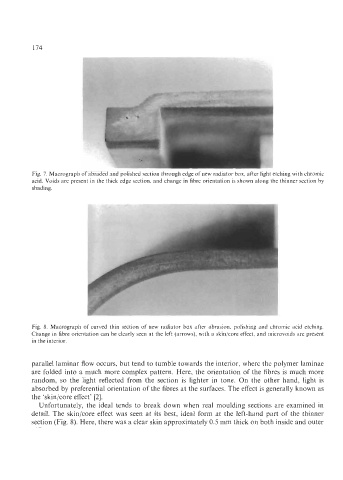
Fig. 7. Macrograph of abraded and polished section through edge of new radiator box, after light etching with chromic
acid. Voids are present in the thick edge section, and change in fibre orientation is shown along the thinner section by
shading.
i
Fig. 8. Macrograph of curved thin section of new radiator box after abrasion, polishing and chromic acid etching.
Change in fibre orientation can be clearly seen at the left (arrows), with a skin/core effect, and microvoids are present
in the interior.
parallel laminar flow occurs, but tend to tumble towards the interior, where the polymer laminae
are folded into a much more complex pattern. Here, the orientation of the fibres is much more
random, so the light reflected from the section is lighter in tone. On the other hand, light is
absorbed by preferential orientation of the fibres at the surfaces. The effect is generally known as
the ‘skin/core effect’ [2].
Unfortunately, the ideal tends to break down when real moulding sections are examined in
detail. The skin/core effect was seen at its best, ideal form at the left-hand part of the thinner
section (Fig. 8). Here, there was a clear skin approximately 0.5 mm thick on both inside and outer