
Page 278 - Failure Analysis Case Studies II
P. 278
263
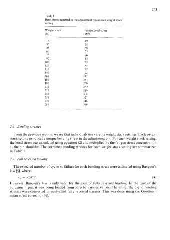
Table 1
Bend stress incurred in the adjustment pin at each weight stack
setting
Weight stack Fatigue bend stress
Ob) (MW
15 19
30 38
45 58
60 17
75 96
90 115
105 135
120 154
135 173
150 192
I65 212
180 23 1
195 250
210 269
225 289
240 308
255 327
270 346
285 366
2.6. Bending stresses
From the previous section, we see that individuals use varying weight stack settings. Each weight
stack setting produces a unique bending stress in the adjustment pin. For each weight stack setting,
the bend stress was calculated using equation (2) and multiplied by the fatigue stress concentration
at the pin shoulder. The corrected bending stresses for each weight stack setting are summarized
in Table 1.
2.7. Full reuersed loading
The expected number of cycles to failure for each bending stress were estimated using Basquin’s
law [5], where,
om = A(NJb. (4)
However, Basquin’s law is only valid for the case of fully reversed loading. In the case of the
adjustment pin, it was being loaded from zero to various values. Therefore, the cyclic bending
stresses were converted to equivalent fully reversed stresses. This was done using the Goodman
mean stress correction [6],