
Page 275 - Failure Analysis Case Studies II
P. 275
260
3.0
1.)
2..
t.?
2.6
2.a
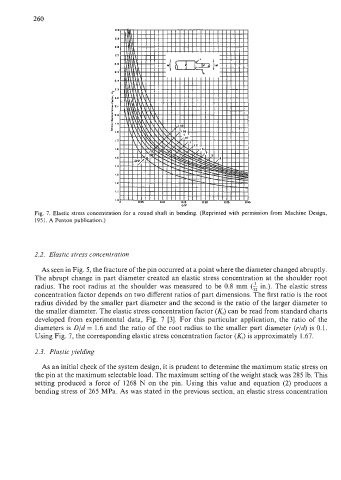
Fig. 7. Elastic stress concentration for a round shaft in bending. (Reprinted with permission from Machine Design,
1951. A Penton publication.)
2.2. Elastic stress concentration
As seen in Fig. 5, the fracture of the pin occurred at a point where the diameter changed abruptly.
The abrupt change in part diameter created an elastic stress concentration at the shoulder root
radius. The root radius at the shoulder was measured to be 0.8 mm (A in.). The elastic stress
concentration factor depends on two different ratios of part dimensions. The first ratio is the root
radius divided by the smaller part diameter and the second is the ratio of the larger diameter to
the smaller diameter. The elastic stress concentration factor (KJ can be read from standard charts
developed from experimental data, Fig. 7 [3]. For this particular application, the ratio of the
diameters is D/d = 1.6 and the ratio of the root radius to the smaller part diameter (r/d) is 0.1.
Using Fig. 7, the corresponding elastic stress concentration factor (KJ is approximately 1.67.
2.3. Plastic yielding
As an initial check of the system design, it is prudent to determine the maximum static stress on
the pin at the maximum selectable load. The maximum setting of the weight stack was 285 lb. This
setting produced a force of 1268 N on the pin. Using this value and equation (2) produces a
bending stress of 265 MPa. As was stated in the previous section, an elastic stress concentration