
Page 374 - Failure Analysis Case Studies II
P. 374
359
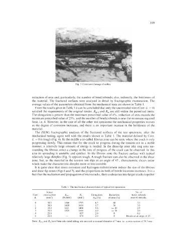
Fig. 3. Corrosion damage of cables.
reduction of area and, particularly, the number of bend/rebends; also, indirectly, the brittleness of
the material. The fractured surfaces were analysed in detail by fractographic examination. The
average values of the parameters obtained from the mechanical tests are shown in Table 1,
From the results given in Table 1 it can be concluded that only the uncorroded wire (Corr. d. = 0)
satisfied the requirements of the original tender. R,,,z and R, are still within the permitted limits.
The elongation is greater than the minimum prescribed value of 4%, reduction of area exceeds the
minimum prescribed value of 25%, and the number of bends/rebends is near the minimum required
limit, i.e. 4. However, in the case of all the other test specimens the mechanical properties worsen
as the degree of corrosion increases, and there is an important increase in the brittleness of the
material.
The (SEM) fractographic analyses of the fractured surfaces of the test specimens, after the
mechanical testing, agree well with the results shown in Table 1. The material defined by Corr.
d. = 0 is tough (Fig. 4). In the middle a so-called fibrous zone can be seen, where the crack is only
progressing slowly. This means that for the crack to progress during the tension test in a stable
manner, a relatively large amount of energy is needed. In the shear-lip zone (the ring area sur-
rounding the fibrous zone) a change in the rate of progress of the crack can be observed. In this
area its spreading is unstable and quicker. In the fibrous zone the fracture surface with typical
relatively large dimples (Fig. 5) appears tough. A tough fracture can also be observed in the shear
zone, but, as the material in the tension test slips at an angle of 45”, characteristic shears occur
which make the characteristic dimples more or less invisible.
It is quite clear that stress corrosion and hydrogen embrittlement reduce the size of the fibrous
and shear-lip zones (Figs 6 and 7), and the proportions in both of brittle locations increases. It is a
fact that the nucleation and propagation of microcracks, their coalescence into larger cracks together
Table 1. The mechanical characteristics of typical test specimens
Actual No. of
Corr. cross-section 4.0 R, Elongation Reduction bendslrebends
2
d. (mm’) (Nimm’) (mm’) Am (%) of area (%) over 45 mm dia.
0 38.5 1546 1793 6.3 40 3.5
1 38.0 1418 1616 5.1 36 3.0
2 35.0 1221 1408 5.6 ca. 20 2.5
3 35.0 1325 1546 2.9 ca. 20 2.0
4 25.0 - 857 2.0 0 0.5
5 22.0 - 878 2.0 0 Breaks at an angle of 25
Note: RN2 and R, have been calculated taking into account a nominal diameter of 7 mm, 1.e. a cross-section of 38.5 mm’.