
Page 411 - Failure Analysis Case Studies II
P. 411
395
can be used to detect, with high sensitivity, deformation and fracture in a material [16]. As HE is
characterised by the tendency to crack leading to failure at reduced ductility, acoustic emission
techniques (AET) can be applied to detect hydrogen embrittlement failure. It has been shown that
AE as a result of HE and stress corrosion cracking (SCC) provides information on the crack
growth process in greater detail than is otherwise possible [17-191. Hartbower et a1 [18] monitored
crack initiation and propagation during SCC of maraging steel, and their results could be excellently
correlated with the cumulative counts of the AE signals. Dunegan and Tetelman [19] have also
used this technique to monitor the onset of unstable fracture in hydrogen charged 4340 steel test
specimens and bolts under constant load. They proposed a power law relationship between count
rate and stress intensity factor and suggested a critical AE rate at onset of rapid fracture. Similar
studies by Parida and Bhattacharya [20], on bend specimens of the same steel, have shown that
the incubation time to nucleate microcracks can be monitored in terms of some directly observable
AE parameters.
2. Investigation
High strength steel wire rods which are used for manufacturing steel ropes, in a local industry,
have been found to be failing at the final stage of production [21]. Stelmor cooled billets of
120 x 120 mm2 having a nominal composition of C-0.82, Mn-0.7, Si4.2, S-0.02 max. and
P4.02 max., are hot-rolled in stages to 12 mm diameter wire rods, which are first pickled and
baked at 150°C for 15 min, followed by flux coating. The wires are then pre-drawn to 10 mm
diameter before patenting. A gap of 10 h is allowed between coating and pre-drawing and patenting.
Subsequent to the patenting process, the wires are again pickled and dipped in hot water and
drawn through a flux to 6 mm diameter. This is followed by galvanising and final drawing to 4.15
mm diameter followed by stranding/spooling.
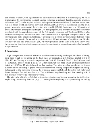
The wire rods, which have failed at various stages during spooling and stranding, typically show
a split along the drawing direction (Fig. 1). The longitudinal splitting into layers during the rolling
Fig. 1. Wire rod showing a typical split failure.