
Page 413 - Failure Analysis Case Studies II
P. 413
397
4. Results
4.1. Microscopy
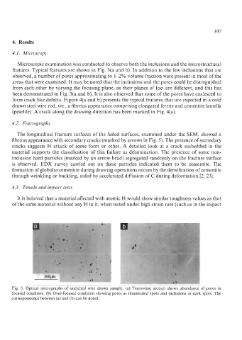
Microscopic examination was conducted to observe both the inclusions and the microstructural
features. Typical features are shown in Fig. 3(a and b). In addition to the few inclusions that are
observed, a number of pores approximating to 1-2% volume fraction were present in most of the
areas that were examined. It may be noted that the inclusions and the pores could be distinguished
from each other by varying the focusing plane, as their planes of foci are different, and this has
been demonstrated in Fig. 3(a and b). It is also observed that some of the pores have coalesced to
form crack like defects. Figure 4(a and b) presents the typical features that are expected in a cold
drawn steel wire rod, viz., a fibrous appearance comprising elongated ferrite and cementite lamella
(pearlite). A crack along the drawing direction has been marked in Fig. 4(a).
4.2. Fractography
The longitudinal fracture surfaces of the failed surfaces, examined under the SEM, showed a
fibrous appearance with secondary cracks (marked by arrows in Fig. 5). The presence of secondary
cracks suggests H attack of some form or other. A detailed look at a crack embedded in the
material supports the classification of this failure as delamination. The presence of some non-
inclusion hard particles (marked by an arrow head) segregated randomly on the fracture surface
is observed. EDX survey carried out on these particles indicated them to be cementite. The
formation of globular cementite during drawing operations occurs by the densification of cementite
through wrinkling or buckling, aided by accelerated diffusion of C during deformation [2,23].
4.3. Tensile and impact tests
It is believed that a material affected with atomic H would show similar toughness values as that
of the same material without any H in it, when tested under high strain rate (such as in the impact
Fig. 3. Optical micrographs of unetched wire drawn sample. (a) Transverse section shows abundance of pores in
focused condition. (b) Over-focused condition showing pores as illuminated spots and inclusions as dark spots. The
correspondence between (a) and (b) can be noted.