
Page 449 - Failure Analysis Case Studies II
P. 449
432
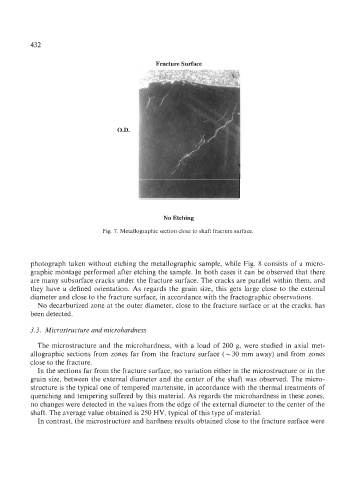
Fracture Surface
O.D.
No Etching
Fig. 7. Metallographic section close to shaft fracture surface.
photograph taken without etching the metallographic sample, while Fig. 8 consists of a micro-
graphic montage performed after etching the sample. In both cases it can be observed that there
are many subsurface cracks under the fracture surface. The cracks are parallel within them, and
they have a defined orientation. As regards the grain size, this gets large close to the external
diameter and close to the fracture surface, in accordance with the fractographic observations.
No decarburized zone at the outer diameter, close to the fracture surface or at the cracks, has
been detected.
3.3. Microstructure and microhardness
The microstructure and the microhardness, with a load of 200 g, were studied in axial met-
allographic sections from zones far from the fracture surface (- 30 mm away) and from zones
close to the fracture.
In the sections far from the fracture surface, no variation either in the microstructure or in the
grain size, between the external diameter and the center of the shaft was observed. The micro-
structure is the typical one of tempered martensite, in accordance with the thermal treatments of
quenching and tempering suffered by this material. As regards the microhardness in these zones,
no changes were detected in the values from the edge of the external diameter to the center of the
shaft. The average value obtained is 250 HV, typical of this type of material.
In contrast, the microstructure and hardness results obtained close to the fracture surface were