
Page 57 - Failure Analysis Case Studies II
P. 57
42
- 8.0
- 6.0
- 4.0
Dune Sand BackfN
- 2.0
- 0.0
17.5 4
unit
weight cohesion
~/m3
18.5
16.0
20.0
I Clay Back Fill
___ ~ ~~
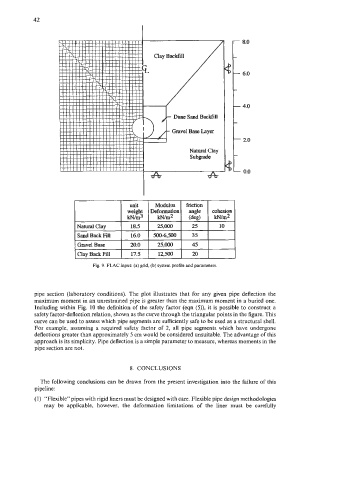
Fig. 9. FLAC input: (a) grid, (b) system profile and parameters.
pipe section (laboratory conditions). The plot illustrates that for any given pipe deflection the
maximum moment in an unrestrained pipe is greater than the maximum moment in a buried one.
Including within Fig. 10 the definition of the safety factor (eqn (5)), it is possible to construct a
safety factor-deflection relation, shown as the curve through the triangular points in the figure. This
curve can be used to assess which pipe segments are sufficiently safe to be used as a structural shell.
For example, assuming a required safety factor of 2, all pipe segments which have undergone
deflections greater than approximately 5 cm would be considered unsuitable. The advantage of this
approach is its simplicity. Pipe deflection is a simple parameter to measure, whereas moments in the
pipe section are not.
8. CONCLUSIONS
The following conclusions can be drawn from the present investigation into the failure of this
pipeline:
(1) ‘‘Flexible” pipes with rigid liners must be designed with care. Flexible pipe design methodologies
may be applicable, however, the deformation limitations of the liner must be carefully