
Page 540 - Fair, Geyer, and Okun's Water and wastewater engineering : water supply and wastewater removal
P. 540
JWCL344_ch13_457-499.qxd 8/7/10 8:49 PM Page 498
498 Chapter 13 Hydraulics of Sewer Systems
L, m Overland flow
70 m
30 m Overland
flow
Gutter flow
Storm sewer
Sewer MH x, m
MH
30 m Inlet
Overland
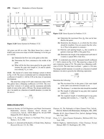
flow Figure 13.21 Sewer System for Problem 13.33.
Flow in Inlets (a) Determine the maximum flow, Q g , that can be han-
gutters dled by the gutter.
(b) Determine the distance, L, at which the first inlets
Figure 13.20 Sewer System for Problem 13.32.
should be installed. (You can assume that the veloc-
ity of flow in the gutters is constant.)
All grates are 60 cm wide. The Main Street has a slope of (c) Find the curb opening length, L T , that would be re-
0.0625 and a transverse slope of 0.050. Manning’s n for the gut- quired to intercept 100% of the gutter flow.
ter is 0.018. (d) Determine the length of the undepressed curb inlet if
it needs to capture 80% of the flow.
(a) Determine the flow rate in the gutter at the inlet.
(b) Determine the flow contained in the width of the 13.33 A residential area with an estimated runoff coefficient
grate. C 0.65 is shown in Fig. 13.21. The street has a slope of 6%
and a transverse slope of 3%. The gutter has a Manning coeffi-
(c) What will be the flow intercepted by the grate inlet? cient of 0.018. The inlet time (overland gutter) is 16.6 min.
Assume the grate inlet length is 2 m and its splash-
over velocity, V 0 , is 1 m/s. The design rainfall intensity (i in mm/h) as a function of rainfall
duration (t in min) is given by the following expression:
13.32 The layout of a storm water drainage system is shown
in Fig. 13.20. The area is residential and it is estimated that the 2,000
i =
coefficient of runoff, C, will be 0.50 at the time of maximum t + 25
development.
Determine the following:
The street has a slope of 2% and a transverse slope of 4%.
The gutters have a Manning coefficient n of 0.016. The over- (a) The maximum flow in the gutter, if the water depth
land flow velocity is 6 m/min and the maximum allowable at the curb is not allowed to exceed 12 cm
depth of water at the curb is 100 mm. The design rainfall inten- (b) The distance at which the inlet should be installed
sity (i in mm/h) as a function of rainfall duration (t in min) for (c) The length of submerged in-sag grate inlet required
the area is:
(assume C o 0.60)
810 (d) The required length of unsubmerged in-sag grate
i =
t + 11 opening inlet (assume C w 3 and W g 40 cm).
BIBLIOGRAPHY
American Society of Civil Engineers and Water Environment Chanson, H., The Hydraulics of Open Channel Flow, 2nd ed.,
Federation, Gravity Sanitary Sewer Design and Elsevier Butterworth-Heinemann, Burlington, MA, 2004.
Construction, 2nd ed., ASCE Manual No. 60 and WEF Chaudry, M. H., Open-Channel Flow, 2nd ed., Springer-Verlag
Manual No. FD-5, Reston, VA, 2007. New York, 2007.
Camp, T. R., Design of Sewers to Facilitate Flow, Sewage Chow, V. T., Open-Channel Hydraulics, McGraw-Hill, New
Works J., 18, 3, 1946. York, 1959.
Cassidy, J. J., Generalized Hydraulics of Grade Inlets, Highway Federal Highway Administration, Urban Drainage Design
Research Record, 123, 36, 1966. Manual, HEC-22, Washington, DC, 1996.