
Page 450 - Fiber Bragg Gratings
P. 450
9.3 Phase and temporal response of Bragg gratings 427
been used to locate gratings. In the next section we will consider the
OLCR method and side-scatter as two techniques to assess Bragg gratings.
Optical low-coherence reflectometry
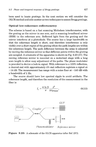
The scheme is based on a fast scanning Michelson interferometer, with
the grating as the mirror in one arm, and a scanning broadband mirror
(BBM) in the reference arm. Reflected light from the grating and the
mirror interferes at a photodiode. The source has a large bandwidth so
that the coherence length is short, and therefore interference is only
visible over a short region of the grating when the path lengths are within
the coherence length. The path difference between the arms is adjusted
by moving the reference mirror so that different points within the grating
are sampled. A schematic of the apparatus is shown in Fig. 9.20 [37]. The
moving reference mirror is mounted on a motorized stage with a long
scan length to allow easy adjustment of the paths. The phase modulator
is provided to derive a lock-in signal. With reference to a 100% reflection,
a cleaved end with approximately 4% end reflection registers a signal at
— 14 dB. The measurement has range with a noise floor at —140 dB with
a bandwidth of 1 Hz.
The source should have low spectral ripple to avoid artifacts. The
coherence length, and therefore the resolution of the measurement in the
fiber is
Figure 9.20: A schematic of the OLCR apparatus (after Ref. [37]).