
Page 452 - Fiber Bragg Gratings
P. 452
9.3 Phase and temporal response of Bragg gratings 429
the source. The free parameter is the refractive index modulation of the
sinusoidal period, since the Bragg wavelength is known, and the length of
the grating is found from the length of the scan between the start of the
spectrum and the reflection at the end of the grating. The zeroes of the OLCR
spectrum are a very sensitive function of the refractive index modulation
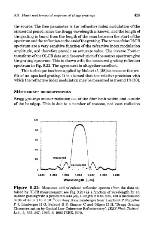
amplitude, and therefore provide an accurate value. The inverse Fourier
transform of the OLCR data and deconvolution of the source spectrum give
the grating spectrum. This is shown with the measured grating reflection
spectrum in Fig. 9.22. The agreement is altogether excellent.
This technique has been applied by Malo et al. [38] to measure the pro-
file of an apodized grating. It is claimed that the relative precision with
which the refractive index modulation may be measured is around 1% [30].
Side-scatter measurements
Bragg gratings scatter radiation out of the fiber both within and outside
of the bandgap. This is due to a number of reasons, not least radiation
Figure 9.22: Measured and calculated reflection spectra (from the data ob-
tained by OLCR measurement; see Fig. 9.21) as a function of wavelength for an
in-fiber grating with a period of 0.443 /am, a length of 0.84 mm, and a modulation
3
depth of An = 1.16 X 10~ (courtesy Hans Limberger from: Lambelet P, Fonjallaz
P Y, Limberger H G, Salathe R P, Zimmer C and Gilgen H H, "Bragg Grating
Characterization by Optical Low-Coherence Reflectometry", IEEE Phot. Technol.
Lett., 5, 565-567, 1993. © 1993 IEEE. [30]).