Page 189 - Finite Element Analysis with ANSYS Workbench
P. 189

180                          Chapter 9  Heat Transfer Analysis


                                                      Y


                                                                            
                                                              k   237 W/m- C

                                                    1
                                                            2
                                   8                                      h   40 W/m - C
                                                                                      2 
                                                                                 
                                                                          T   30 C
                                   2                                       

                               Z

                                                             2                  X
                                                                    15
                                       q  1500 W/m 2


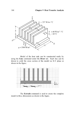
                                         Model  of  the  heat  sink  can  be  constructed  easily  by
                              using the  Line command under the Draw tab.   Each line can  be
                              drawn  to  yield  the  cross  section  of  the  model  on  X-Y  plane  as
                              shown in the figure.


                                         The Extrude command is used to create the  complete
                              model in three dimensions as shown in the figure.
   184   185   186   187   188   189   190   191   192   193   194