Page 199 - Finite Element Analysis with ANSYS Workbench
P. 199

190                       Chapter 10  Thermal Stress Analysis


                                                      F
                                          The  vector   for  two-  and  three-dimensional  ele-
                                                       0
                              ment types can be derived without difficulty.  The finite element
                              equations for both heat transfer and solid stress problems suggest
                              that  the  process  for  solving  thermal  stress  problem  is  straight
                              forward.  Again, to avoid difficulty of transferring nodal tempera-
                              tures from the heat transfer analysis to the solid stress analysis, a
                              common finite element mesh should be used.
                                          We will use ANSYS through the Workbench to carry
                              out the thermal stress analysis for both academic and application
                              problems as demonstrated in the following section.


                              10.3  Academic Example

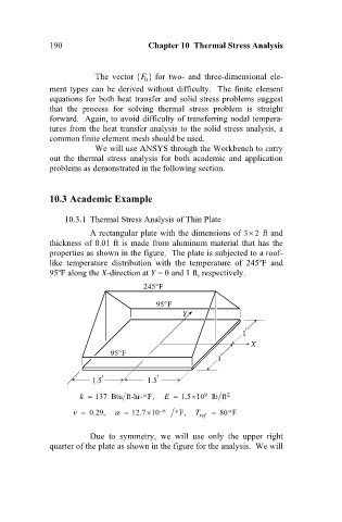
                                  10.3.1  Thermal Stress Analysis of Thin Plate
                                         A rectangular plate with the dimensions of 32  ft and
                              thickness of 0.01 ft is made from aluminum material that has the
                              properties as shown in the figure.  The plate is subjected to a roof-
                                                                                     
                              like  temperature  distribution  with  the  temperature  of  245 F  and
                                
                              95 F along the X-direction at Y = 0 and 1 ft, respectively.
                                                          
                                                       245 F
                                                            
                                                          95 F
                                                                 Y

                                                                                 1 '
                                                                                   X
                                                
                                              95 F
                                                                          1 '
                                         1.5 '          1.5 '

                                                                    
                                      k   137 Btu ft-hr- F,  E   1.5 10 lb ft 2
                                                                       9
                                                       o
                                        0.29,       12.7 10  6  o  F,  T ref    80 F
                                                        
                                                                             o

                                         Due  to  symmetry,  we  will  use  only  the  upper  right
                              quarter of the plate as shown in the figure for the analysis.  We will
   194   195   196   197   198   199   200   201   202   203   204