
Page 44 - Finite Element Analysis with ANSYS Workbench
P. 44
2.3 Academic Example 35
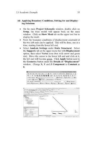
(d) Applying Boundary Conditions, Solving for and Display-
ing Solutions
On the main Project Schematic window, double click on
Setup, the truss model will appear back on the main
window. Click on Show Mesh tab on the upper tool bar to
display the mesh.
Next, the boundary conditions of displacement constraint at
the two left ends can be applied. This will be done, one at a
time, starting from the lower left end.
Select Analysis Settings under Static Structural. Select
the Supports tab on the upper menu bar with Displacement
option, then select Vertex icon (box with arrow and green
dot). Move the cursor to the lower left end and click at it,
the left end will become green. Click Apply button next to
the Geometry button under the Details of “Displacement”
window. Change X, Y and Z Component to Constant as
0.