
Page 40 - Finite Element Analysis with ANSYS Workbench
P. 40
2.3 Academic Example 31
Right click on the Geometry tab and select the New
Geometry…. This will launch the ANSYS Design
Modeler (green logo DM).
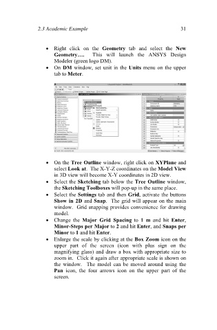
On DM window, set unit in the Units menu on the upper
tab to Meter.
On the Tree Outline window, right click on XYPlane and
select Look at. The X-Y-Z coordinates on the Model View
in 3D view will become X-Y coordinates in 2D view.
Select the Sketching tab below the Tree Outline window,
the Sketching Toolboxes will pop-up in the same place.
Select the Settings tab and then Grid, activate the buttons
Show in 2D and Snap. The grid will appear on the main
window. Grid snapping provides convenience for drawing
model.
Change the Major Grid Spacing to 1 m and hit Enter,
Minor-Steps per Major to 2 and hit Enter, and Snaps per
Minor to 1 and hit Enter.
Enlarge the scale by clicking at the Box Zoom icon on the
upper part of the screen (icon with plus sign on the
magnifying glass) and draw a box with appropriate size to
zoom in. Click it again after appropriate scale is shown on
the window. The model can be moved around using the
Pan icon, the four arrows icon on the upper part of the
screen.