
Page 35 - Finite Element Analysis with ANSYS Workbench
P. 35
26 Chapter 2 Truss Analysis
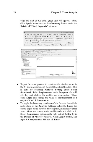
edge and click at it, a small green spot will appear. Then,
click Apply button next to the Geometry button under the
Details of “Fixed Supports” window.
Repeat the same process to constrain the displacements in
the Y- and Z-directions of the middle and right nodes. This
is done by selecting Analysis Setting under Static
Structural. Select Displacement under Supports tab, hold
Ctrl key and click at the middle and right nodes. Then,
click Apply and change the value of Displacement to 0
only for Y and Z Component.
To apply the boundary condition of the force at the middle
node, click on the Analysis Settings, select the Loads tab
on the upper menu bar with Force option, and select Vertex
icon. Move the cursor to the middle node and click at it.
Select Components option on the right side of Define By in
the Details of “Force” window. Click Apply button, and
input X Component as 300 and hit Enter.