
Page 34 - Finite Element Analysis with ANSYS Workbench
P. 34
2.3 Academic Example 25
Repeat the same process to assign Material 2 containing
material properties of the right element to the second Line
Body.
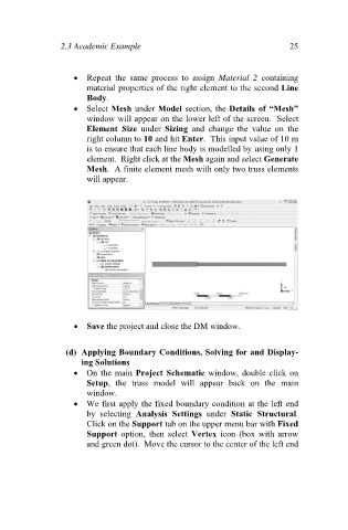
Select Mesh under Model section, the Details of “Mesh”
window will appear on the lower left of the screen. Select
Element Size under Sizing and change the value on the
right column to 10 and hit Enter. This input value of 10 m
is to ensure that each line body is modelled by using only 1
element. Right click at the Mesh again and select Generate
Mesh. A finite element mesh with only two truss elements
will appear.
Save the project and close the DM window.
(d) Applying Boundary Conditions, Solving for and Display-
ing Solutions
On the main Project Schematic window, double click on
Setup, the truss model will appear back on the main
window.
We first apply the fixed boundary condition at the left end
by selecting Analysis Settings under Static Structural.
Click on the Support tab on the upper menu bar with Fixed
Support option, then select Vertex icon (box with arrow
and green dot). Move the cursor to the center of the left end