
Page 30 - Finite Element Analysis with ANSYS Workbench
P. 30
2.3 Academic Example 21
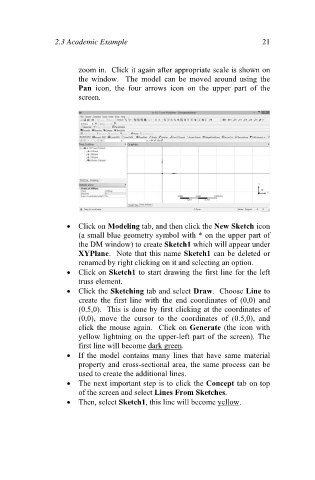
zoom in. Click it again after appropriate scale is shown on
the window. The model can be moved around using the
Pan icon, the four arrows icon on the upper part of the
screen.
Click on Modeling tab, and then click the New Sketch icon
(a small blue geometry symbol with * on the upper part of
the DM window) to create Sketch1 which will appear under
XYPlane. Note that this name Sketch1 can be deleted or
renamed by right clicking on it and selecting an option.
Click on Sketch1 to start drawing the first line for the left
truss element.
Click the Sketching tab and select Draw. Choose Line to
create the first line with the end coordinates of (0,0) and
(0.5,0). This is done by first clicking at the coordinates of
(0,0), move the cursor to the coordinates of (0.5,0), and
click the mouse again. Click on Generate (the icon with
yellow lightning on the upper-left part of the screen). The
first line will become dark green.
If the model contains many lines that have same material
property and cross-sectional area, the same process can be
used to create the additional lines.
The next important step is to click the Concept tab on top
of the screen and select Lines From Sketches.
Then, select Sketch1, this line will become yellow.