
Page 25 - Finite Element Analysis with ANSYS Workbench
P. 25
16 Chapter 2 Truss Analysis
u 1 u 2
F F
1
1 A, E 2 2
x
L
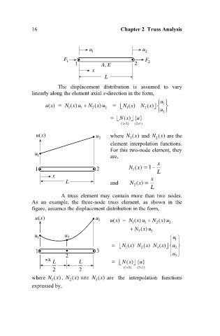
The displacement distribution is assumed to vary
linearly along the element axial x-direction in the form,
u 1
() Nx u
ux 1 () 1 N 2 ( ) u Nx 2 () x
x
() N
2
1
u
2
N () x
u
(1 2) (2 1)
ux u 2 where Nx and Nx are the
()
()
()
2
1
element interpolation functions.
For this two-node element, they
u 1 are,
x
()
1 2 Nx 1
1
L
x
L and Nx x
()
2
L
A truss element may contain more than two nodes.
As an example, the three-node truss element, as shown in the
figure, assumes the displacement distribution in the form,
()
ux u 3 ux N 1 () u N 2 ( ) u 2
()
x
x
1
Nx 3
() u
3
u 1 u 2 u 1
x
x
u
Nx N 2 () N 3 ()
()
2
1
1 3
u
x L 2 L N () x 3
u
2 2 (1 3) (3 1)
where Nx , Nx 3 ()
()
() และ Nx are the interpolation functions
2
1
expressed by,