
Page 28 - Finite Element Analysis with ANSYS Workbench
P. 28
2.3 Academic Example 19
enter the Poisson Ratio value as 0.3 and hit Enter, and
close this window.
Repeat the same process to provide data of the second
material with the Young’s Modulus of 10e7 and Poisson
Ratio of 0.3 and assign the name as “Material 2”.
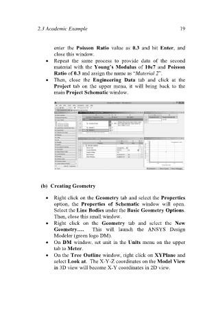
Then, close the Engineering Data tab and click at the
Project tab on the upper menu, it will bring back to the
main Project Schematic window.
(b) Creating Geometry
Right click on the Geometry tab and select the Properties
option, the Properties of Schematic window will open.
Select the Line Bodies under the Basic Geometry Options.
Then, close this small window.
Right click on the Geometry tab and select the New
Geometry…. This will launch the ANSYS Design
Modeler (green logo DM).
On DM window, set unit in the Units menu on the upper
tab to Meter.
On the Tree Outline window, right click on XYPlane and
select Look at. The X-Y-Z coordinates on the Model View
in 3D view will become X-Y coordinates in 2D view.