
Page 31 - Finite Element Analysis with ANSYS Workbench
P. 31
22 Chapter 2 Truss Analysis
Click Apply icon on the right side of the Base Objects tab
in the Details View window at the lower left of the screen.
The line will become cyan, then click on Generate. The
right side of the Base Objects tab will show 1 Sketch. The
1 Part, 1 Body item will appear in the Tree Outline
window.
To draw the second line representing the right element,
select New Sketch, the item Sketch 2 will pop up beneath
Sketch 1. The second line that connects between the
coordinates of (0.5,0) and (1.5,0) can be drawn using the
same process. Then, select Concept and Lines From
Sketches.
Select Sketch 2, this second line will become yellow.
Before clicking on Apply button, be sure to change Add
Material on the right side of Operation in the Details
View window to Add Frozen. Without doing this, by
default, the two lines would become a single line and only
one material property is allowed.
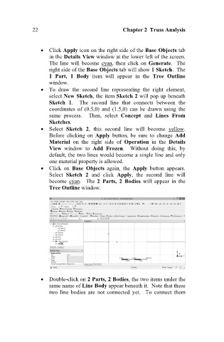
Click on Base Objects again, the Apply button appears.
Select Sketch 2 and click Apply, the second line will
become cyan. The 2 Parts, 2 Bodies will appear in the
Tree Outline window.
Double-click on 2 Parts, 2 Bodies, the two items under the
same name of Line Body appear beneath it. Note that these
two line bodies are not connected yet. To connect them