
Page 36 - Finite Element Analysis with ANSYS Workbench
P. 36
2.3 Academic Example 27
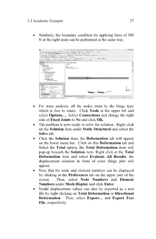
Similarly, the boundary condition for applying force of 500
N at the right node can be performed in the same way.
For truss analysis, all the nodes must be the hinge type
which is free to rotate. Click Tools at the upper tab and
select Options…. Select Connections and change the right
side of Fixed Joints to No and click OK.
The problem is now ready to solve for solution. Right click
on the Solution item under Static Structural and select the
Solve tab.
Click the Solution item, the Deformation tab will appear
on the lower menu bar. Click on this Deformation tab and
Select the Total option, the Total Deformation item will
pop-up beneath the Solution item. Right click at the Total
Deformation item and select Evaluate All Results, the
displacement solution in form of color fringe plot will
appear.
Note that the node and element numbers can be displayed
by clicking at the Preferences tab on the upper part of the
screen. Then, select Node Numbers and Element
Numbers under Mesh Display and click Enter.
Nodal displacement values can also be exported as a text
file by right clicking on Total Deformation or Directional
Deformation. Then, select Export… and Export Text
File, respectively.