
Page 45 - Finite Element Analysis with ANSYS Workbench
P. 45
36 Chapter 2 Truss Analysis
Repeat the same process to apply boundary condition of
zero displacement for X, Y and Z Components at the upper
left end.
Repeat the same process to apply boundary condition of
zero displacement only for the Z Component at the lower
right end. Note that the Z displacement must be zero for all
nodes of the 2D planar truss problems.
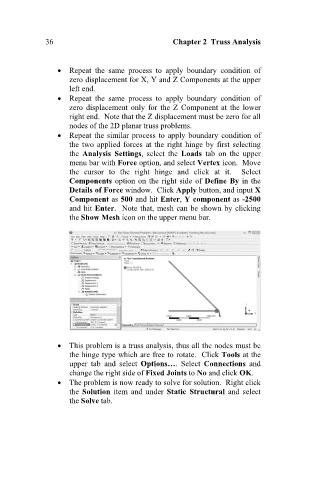
Repeat the similar process to apply boundary condition of
the two applied forces at the right hinge by first selecting
the Analysis Settings, select the Loads tab on the upper
menu bar with Force option, and select Vertex icon. Move
the cursor to the right hinge and click at it. Select
Components option on the right side of Define By in the
Details of Force window. Click Apply button, and input X
Component as 500 and hit Enter, Y component as -2500
and hit Enter. Note that, mesh can be shown by clicking
the Show Mesh icon on the upper menu bar.
This problem is a truss analysis, thus all the nodes must be
the hinge type which are free to rotate. Click Tools at the
upper tab and select Options…. Select Connections and
change the right side of Fixed Joints to No and click OK.
The problem is now ready to solve for solution. Right click
the Solution item and under Static Structural and select
the Solve tab.