Page 48 - Finite Element Analysis with ANSYS Workbench
P. 48

2.4 Application                                            39


                                 2.4   Application

                                     2.4.1  Twenty-one Truss Members in Two Dimensions

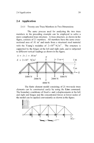
                                           The  same  process  used  for  analyzing  the  two  truss
                                 members  in  the  preceding  example  can  be  employed  to  solve  a
                                 more complicated truss structure.  A truss structure, as shown in the
                                 figure, consists of 21 members.  All members have the same cross-
                                                      2
                                 sectional area of .01 m  and made from a structural steel material
                                                                           2
                                 with  the  Young’s  modulus  of  210  11  Nm .    The  structure  is
                                 supported by the hinges at the left and right ends, and is subjected
                                 to different vertical loadings as shown in the figure.
                                  A   .1 .1   .01m 2
                                        
                                                             Y
                                        
                                 E   210  11  N m 2                    5 m            1 m


                                                                                       5 m
                                                                                            X

                                         1000 N                           1000 N
                                                  2000 N          2000 N

                                                          4000 N
                                         The finite element model consisting of 21 two-node truss
                                 elements  can  be  constructed  easily  by  using  the  Line  command.
                                 The boundary conditions of fixed x- and y-displacements at the left
                                 and right end hinges and the concentrated forces at lower nodes of
                                 the model can be applied conveniently as shown in the figure.
   43   44   45   46   47   48   49   50   51   52   53