
Page 46 - Finite Element Analysis with ANSYS Workbench
P. 46
2.3 Academic Example 37
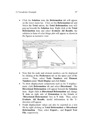
Click the Solution item, the Deformation tab will appear
on the lower menu bar. Click on this Deformation tab and
Select the Total option, the Total Deformation item will
pop-up beneath the Solution item. Right click at the Total
Deformation item and select Evaluate All Results, the
solution in form of color fringe plot will appear as shown in
the figures as isometric view.
Note that the node and element numbers can be displayed
by clicking at the Preferences tab on the upper part of the
screen. Then, select Node Numbers and Element
Numbers under Mesh Display and click Enter.
To show displacement components such as the Y-displace-
ment, click Deformation tab and select Directional. The
Directional Deformation will appear beneath the Solution
item. Right click at Directional Deformation and change
X Axis on right side of Orientation in the Details of
“Directional Deformation” box to Y Axis. Then, select
Evaluate All Results, model deformation in the Y-
direction will appear.
Nodal displacement values can also be exported as a text
file by right clicking on Total Deformation or Directional
Deformation. Then, select Export… and Export Text
File, respectively.